banner


How To Clean Ps3 Super Slim Fan

Introduction

If your PlayStation 3 Super Slim'due south fan is making unreasonably loud noises or if your device keeps overheating, consider using this guide to supplant it. Earlier post-obit the steps to replace your fan, be sure that you lot have all the tools required to replace it, enough free time to take autonomously your device with intendance, and a make clean and uncluttered working space. Be sure to exist gentle with your device when following these steps to ensure that yous replace your fan correctly.

  1. Remove the side HDD bay cover by sliding the panel towards the back of the device. The bay cover is found on the right side of the device.

    • Remove the side HDD bay cover by sliding the console towards the back of the device.

    • The bay cover is found on the right side of the device.

  2. Remove all three black 9.8mm long screws with a T-8 security screwdriver. Remove the blue 7.9mm long screw with a Phillips #1 screwdriver.

    • Remove all three black 9.8mm long screws with a T-viii security screwdriver.

    • Remove the blue seven.9mm long screw with a Phillips #1 screwdriver.

  3. Pull on the tab to remove the HDD. The HDD should be removed and stored carefully to prevent damage to data.

    • Pull on the tab to remove the HDD.

    • The HDD should be removed and stored carefully to prevent harm to data.

  4. On the bottom of the device, pry out the three rubber feet covers with the metal spudger. Remove the four black 36.3mm long screws underneath with a Phillips #1 screwdriver.

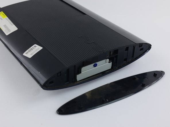
    • On the lesser of the device, pry out the three safe feet covers with the metal spudger.

    • Remove the four black 36.3mm long screws underneath with a Phillips #1 screwdriver.

    • 1 screw is located underneath the warranty sticker. This sticker tin either be peeled off or punctured through with a screwdriver.

  5. On the top of the device, unlatch the hook on the furthest right beneath the front panel, lift the panel slightly and apply pressure. Unlatch the second right-side hook by sliding a plastic opening tool in the marked area.

    • On the top of the device, unlatch the hook on the furthest correct beneath the forepart console, elevator the console slightly and apply pressure.

    • Unlatch the 2d correct-side hook by sliding a plastic opening tool in the marked area.

    • Slide the console to the left to unlatch the rest of the hooks.

    • This is probably the well-nigh difficult office of the process. If you cannot unlatch the claw on the front panel, you can attempt to pry all the hooks off. Withal, practise this at your own risk, as these hooks break hands.

  6. Remove the back panel by pressing down the tab on the right side of the device, and sliding the panel to the left.

    • Remove the back panel by pressing down the tab on the right side of the device, and sliding the panel to the left.

  7. Remove the five silver 20.8mm long screws with a Phillips #1 screwdriver. Remove the two black 9.9mm long screws in the disc reader with a T-8 security screwdriver. Remove the top black plastic shell.

    • Remove the five argent 20.8mm long screws with a Phillips #1 screwdriver.

    • Remove the 2 black nine.9mm long screws in the disc reader with a T-8 security screwdriver.

    • Remove the peak blackness plastic vanquish.

  8. Move the optical drive to the side to reveal one of the silver 8.8mm long screws. Remove the two silver 8.8mm long screws on either side with a Phillips #1 screwdriver. Remove the two silver 8.8mm long screws on either side with a Phillips #1 screwdriver.

    • Move the optical drive to the side to reveal one of the silver 8.8mm long screws.

    • Remove the two silverish eight.8mm long screws on either side with a Phillips #ane screwdriver.

  9. Remove the cable from the plug and remove the wires from the two plastic hooks. When removing the cable from the plug, pull on the plastic male connecter, not on the wires. Remove the power supply unit.

    • Remove the cable from the plug and remove the wires from the two plastic hooks.

    • When removing the cable from the plug, pull on the plastic male person connecter, not on the wires.

    • Remove the power supply unit.

  10. Remove the front white flex-ribbon cable by pulling upward from its base. Remove the black and blue flex-ribbon cable behind it by pulling upward on the black tab, then pulling out the cable. Remove the black and blue flex-ribbon cable behind it by pulling upward on the black tab, then pulling out the cable.

    • Remove the front end white flex-ribbon cablevision by pulling upward from its base.

    • Remove the blackness and blue flex-ribbon cable behind it past pulling up on the black tab, and then pulling out the cable.

  11. Rotate the device 180 degrees. Remove the back white flex-ribbon cable by pulling upward from its base. Remove the optical drive.

    • Rotate the device 180 degrees.

    • Remove the dorsum white flex-ribbon cable by pulling upward from its base.

    • Remove the optical bulldoze.

  12. Locate the white flex ribbon cable that connects the power button to the motherboard. Pull this cable out from the motherboard end. Remove the five black 8.3mm long screws with a Phillips #1 screwdriver. Remove the two silver 12.8mm long screws with a Phillips #1 screwdriver.

    • Locate the white flex ribbon cable that connects the power push to the motherboard. Pull this cablevision out from the motherboard end.

    • Remove the v black 8.3mm long screws with a Phillips #1 screwdriver.

    • Remove the 2 silver 12.8mm long screws with a Phillips #1 screwdriver.

    • Remove the device from the lesser beat casing.

  13. Remove the two black 8.3mm long screws with a Phillips #1 screwdriver from the Wi-Fi antennas. Lift the Wi-Fi antennas off their mount. Lift the Wi-Fi antennas off their mount.

    • Remove the two black viii.3mm long screws with a Phillips #1 screwdriver from the Wi-Fi antennas.

    • Elevator the Wi-Fi antennas off their mount.

  14. Use a plastic opening tool to remove the Wi-Fi wires from their sockets on the motherboard. Remove the wires from the hooks around the motherboard and fan cover to completely remove the antennas. The Wi-Fi antennas' ports are labeled B and W on the motherboard for reassembly.

    • Employ a plastic opening tool to remove the Wi-Fi wires from their sockets on the motherboard.

    • Remove the wires from the hooks around the motherboard and fan cover to completely remove the antennas.

    • The Wi-Fi antennas' ports are labeled B and W on the motherboard for reassembly.

    • To insert your new Wi-Fi antennas, insert the wires of your replacement Wi-Fi antennas into each socket, feed the wires through the hooks, and install the antennas on their mountain.

  15. Remove the two black 14.5mm long screws with a Phillips #1 screwdriver from the center of the bottom metal casing. Remove the four silver 8.7mm long screws with a Phillips #1 screwdriver around the edges of the bottom metal casing. Remove the bottom metal casing.

    • Remove the two black 14.5mm long screws with a Phillips #1 screwdriver from the middle of the bottom metal casing.

    • Remove the four silver 8.7mm long screws with a Phillips #1 screwdriver around the edges of the bottom metallic casing.

    • Remove the lesser metal casing.

  16. Remove the fan wire from its plug on the top metal casing. When removing the wire, do not pull from the wire. Instead, pull from the white plastic male connecter. Remove the motherboard from the top metal casing. Lift from the side with the two USB plugs to avoid damaging the four back ports.

    • Remove the fan wire from its plug on the top metal casing.

    • When removing the wire, do not pull from the wire. Instead, pull from the white plastic male person connecter.

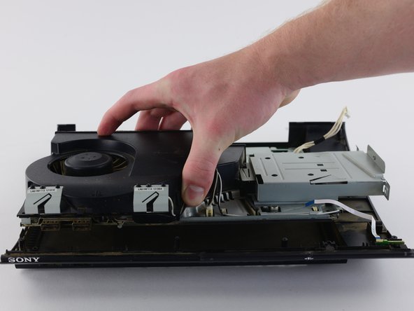
    • Remove the motherboard from the top metallic casing. Lift from the side with the two USB plugs to avoid damaging the four back ports.

    • There is an agglutinative between the top metallic casing and the motherboard in the middle, so you lot may have to apply more strength than usual. Do non force the two pieces apart, but slowly apply more and more pressure level until the adhesive gives.

  17. On the bottom of the top metal casing, remove the three black 8.0mm long screws with a Phillips #1 screwdriver. Remove the fan from the plastic cover. Remove the fan from the plastic cover.

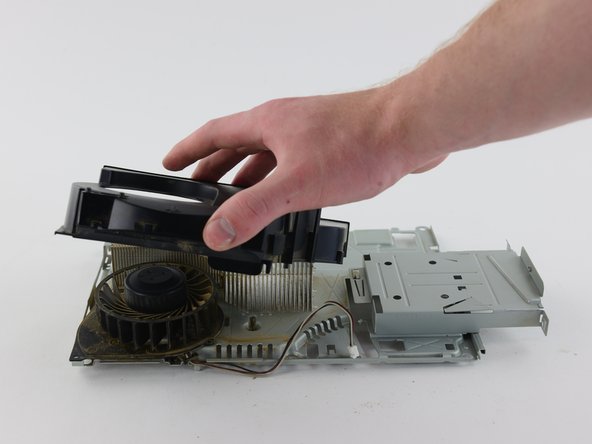
    • On the bottom of the top metal casing, remove the three black 8.0mm long screws with a Phillips #ane screwdriver.

    • Remove the fan from the plastic cover.

Determination

Install the replacement fan. To reassemble your device, follow these instructions in reverse social club.

Squad

Embed this guide

Choose a size and copy the code below to embed this guide as a small widget on your site / forum.

Preview

Source: https://www.ifixit.com/Guide/PlayStation+3+Super+Slim+Fan+Replacement/62768

Posted by: elmorethrodgent.blogspot.com

0 Response to "How To Clean Ps3 Super Slim Fan"

Post a Comment

Iklan Atas Artikel

Iklan Tengah Artikel 1

Iklan Tengah Artikel 2

Iklan Bawah Artikel